CODAN 9323/9360
Series
EXTERNAL, INTERNAL/PCB PICTURES.
The 9323/9360/9390/9780 ran from 1993 to about
2003
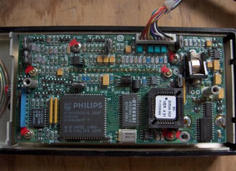
All control head PCBs were SMD. The main
transceiver PCBs were initially
manufactured using through hole construction, but switched to SMD around 2001.
|
Control Head Cross reference:
The 9323 uses the 9330 control head
picture
The 9360 uses the 9366 control head
picture
|
Radio Firmware Version info:
(approx dates)
1993- V1.xx Firmware
1994- V2.xx firmware
1995- V3.xx Firmware
1997- V4.xx Firmware
You must match the head firmware with the transceiver firmware..ie, only use
a V2.xx head with a v2.xx transceiver.
|
|
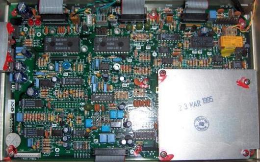
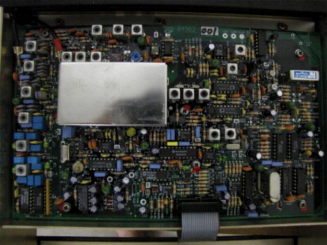
Main Transceiver PCBs:
Through Hole Processor Board.
Through Hole IF Board
|
|
Internal Control Head shots:
LCD
Display Remote Head PCB
Replacement Keypad
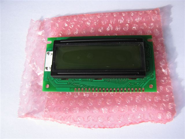

Keypad and LCD Repair Information -
Click Here
|
Microphone Socket Pinouts
| Pin 1 |
Speaker audio out (usually linked to pin 7) |
| Pin 2 |
Microphone audio |
| Pin 3 |
Earth |
| Pin 4 |
Data to Transceiver |
| Pin 5 |
PTT/Data from Transceiver |
| Pin 6 |
13.6 volts supply |
| Pin 7 |
Speaker audio to front panel speaker |
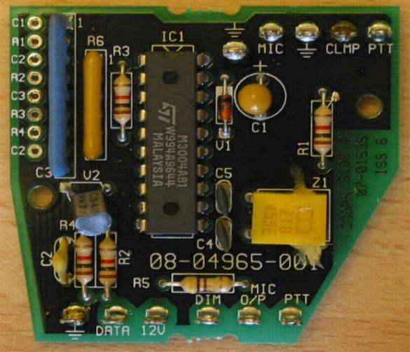
Microphone keypad encoder PCB.
Note: IC1 (above) is actually a I/R remote control encoder Chip.
This means that a standard DTMF Mic will not work on a Codan 9xxx.
Picture By Ian Ross UK Thanks.
Antenna Control Cable Wiring
9350 Antenna Control Cable
Wiring Info for 85xx/9xxx radios:
15 pin D
6 Pin Mil. Connector
Configuration
12, 13
A
+12VDC
14,15
B
Gnd
4
C
Tune
5
D
Scan
11
E
Tuned Indicator
-
F
Not Used
GPS connection
RS232 socket on rear of Main Transceiver.
Tip-Radio data input
Ring-Radio data output
Sleeve- Ground
For a Very Handy Guide on how to Personalise your 9323/9360/9780/9390 via
the
Keypad Menu System
Click Here
9323 Programming lead
Available at www.hf-radio.com.au
Manuals & Handbooks
9323 User
Guide and reference Manual are available at :
www.hfradiosales.com ... Once there,
just Click on the
"Manuals and Downloads" section of the top menu .